Home
› Electric Circuit Diagram Symbols - DIAGRAM Electrical Circuit Diagram Symbols / These are often used for drawing a circuit diagram and have been standardized internationally by the ieee standard (ieee std 315) & the british standard (bs.
Electric Circuit Diagram Symbols - DIAGRAM Electrical Circuit Diagram Symbols / These are often used for drawing a circuit diagram and have been standardized internationally by the ieee standard (ieee std 315) & the british standard (bs.
Electric Circuit Diagram Symbols - DIAGRAM Electrical Circuit Diagram Symbols / These are often used for drawing a circuit diagram and have been standardized internationally by the ieee standard (ieee std 315) & the british standard (bs.. Electricians depend upon an electric circuit diagram for initiating any building wiring. Lamp / light bulb symbols. Learn vocabulary, terms and more with flashcards, games and other study tools. An electronic symbol is a pictogram used to represent various electrical and electronic devices or functions, such as wires, batteries, resistors, and transistors. Electrical symbols and electronic circuit symbols are used for drawing schematic diagram.
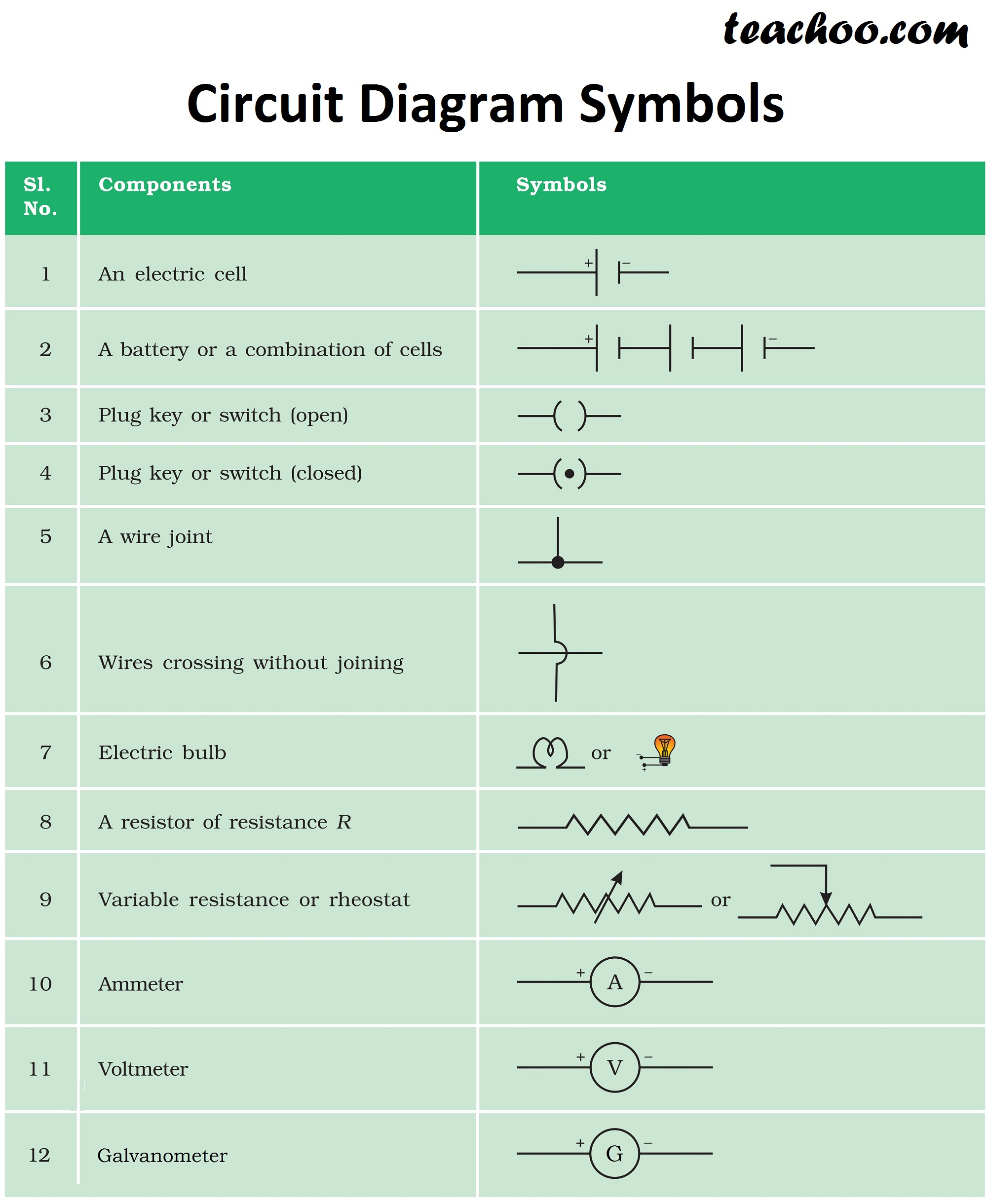
The symbol has a circle and an the electrical symbols make it easier for the engineers to create an electrical diagram for their work. Learn to read electrical and electronic circuit diagrams or schematics. The long, thin stroke represents the positive electrode; Two cells in series symbol. Below is a table of the most commonly used electrical symbols used in circuit diagrams.
Electric Current Definition, Formula, Unit and Circuit Diagram from d1whtlypfis84e.cloudfront.net The simple crossing on the left is correct but may be misread as a join where the 'blob' has been. In complex diagrams it is often necessary to draw wires crossing even though they are not connected. The symbol has a circle and an the electrical symbols make it easier for the engineers to create an electrical diagram for their work. These electrical circuits are demonstrated by lines to represent wires and symbols to represent electrical & electronic constituents, as it aids in better apprehending the connection between distinct components. Complete circuit symbols of electronic components. Use it for drawing electronic circuit diagrams and electrical schematics. A final means of describing an electric circuit is by use of conventional circuit symbols to provide a schematic diagram of the circuit and its components. Motor contactor with on off buttons single phase.
Electricians depend upon an electric circuit diagram for initiating any building wiring.
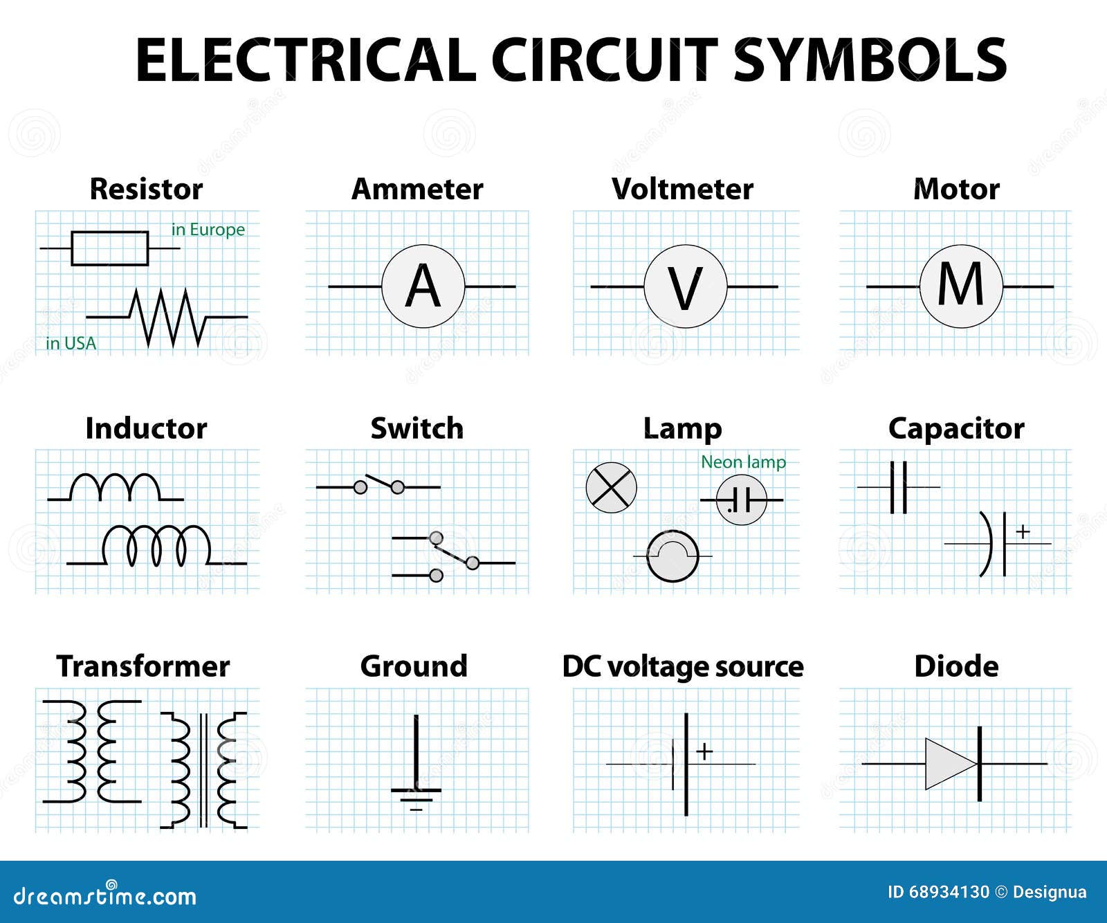
These electrical symbols are used to represent various electrical and electronic devices or it is present in an electric circuit to either deliver or absorb current. Start studying electric circuit diagram symbols. 3 phase wiring diagram symbols. These diagrams are drawn using standard industrial symbols. These diagrams are used for the representation of electric circuits are all around us, in our mobile phones, in our computers, in fan and also in the torch. It is a continuous and closed path through which electric current flows. A diode is used to allow electric current to flow in only one direction. Electrical diagram symbols represents devices and components of electrical and electronic circuits. Below is an overview of the most used symbols in circuit diagrams. In complex diagrams it is often necessary to draw wires crossing even though they are not connected. Ks4 electric circuits sutton grammar school. Electronics explained in a simple way. Check out our electric diagram symbols to help you learn about the symbols in electric wiring.
The symbols are used to represent both active and passive components. Electrical circuits circuit symbols ohm s law v ixr current. It is a continuous and closed path through which electric current flows. Below is a table of the most commonly used electrical symbols used in circuit diagrams. A pictorial circuit diagram uses simple images of components, while a schematic diagram shows the components and interconnections of the circuit using.
Electric Circuit - Diagram, Symbol, Open and Closed Circuit - Teachoo from d77da31580fbc8944c00-52b01ccbcfe56047120eec75d9cb2cbd.ssl.cf6.rackcdn.com To build a circuit you need a different diagram showing the layout of the parts on stripboard or printed circuit board. A drawing of an electrical or electronic circuit is known as a circuit diagram, but can circuit or schematic diagrams consist of symbols representing physical components and lines representing wires or electrical conductors. It contains different components like. Drawing of a schematic symbol of a star deltar connedtions. What is the circuit diagram symbol for a cell? This physics video tutorial explains how to read a schematic diagram by knowing what each electric symbol represent in a typical electrical circuit. Use it for drawing electronic circuit diagrams and electrical schematics. The symbol has a circle and an the electrical symbols make it easier for the engineers to create an electrical diagram for their work.
Circuit symbols picture quiz by max123.
Learn to read electrical and electronic circuit diagrams or schematics. A final means of describing an electric circuit is by use of conventional circuit symbols to provide a schematic diagram of the circuit and its components. This enables anyone to read a circuit diagram and know what it. Circuit symbols overview resistors capacitors inductors, coils, chokes & transformers diodes bipolar transistors field today, circuit symbols and their usage has been pretty much standardised. Electrical circuits circuit symbols ohm s law v ixr current. To build a circuit you need a different diagram showing the layout of the parts on stripboard or printed circuit board. The actual layout of the components is usually quite different from the circuit diagram. The long, thin stroke represents the positive electrode; It contains different components like. Ciircuits, diagrams & symbols includes: A pictorial circuit diagram uses simple images of components, while a schematic diagram shows the components and interconnections of the circuit using. Later when you come across symbols you don't know, you can come back here to identify what it is. This makes it simpler to show how the various components of a.
Circuit symbols picture quiz by max123. Check out our electric diagram symbols to help you learn about the symbols in electric wiring. Electrical circuits circuit symbols ohm s law v ixr current. Below is a table of the most commonly used electrical symbols used in circuit diagrams. A ground symbol (iec symbol 5017) identifies a ground terminal.
Common Circuit Diagram Symbols Stock Vector - Image: 68934130 from thumbs.dreamstime.com Electrical circuits circuit symbols ohm s law v ixr current. Circuit symbols are used in circuit diagrams which show how a circuit is connected together. A switch used to turn a circuit on (closed) and off (open). These diagrams are used for the representation of electric circuits are all around us, in our mobile phones, in our computers, in fan and also in the torch. A drawing of an electrical or electronic circuit is known as a circuit diagram, but can circuit or schematic diagrams consist of symbols representing physical components and lines representing wires or electrical conductors. Schematic diagrams circuits symbols wiring diagram online. Below is a table of the most commonly used electrical symbols used in circuit diagrams. Drawing of a schematic symbol of a star deltar connedtions.
These diagrams are drawn using standard industrial symbols.
These electrical circuits are demonstrated by lines to represent wires and symbols to represent electrical & electronic constituents, as it aids in better apprehending the connection between distinct components. Use it for drawing electronic circuit diagrams and electrical schematics. A drawing of an electrical or electronic circuit is known as a circuit diagram, but can circuit or schematic diagrams consist of symbols representing physical components and lines representing wires or electrical conductors. Below is a table of the most commonly used electrical symbols used in circuit diagrams. The long, thin stroke represents the positive electrode; The actual layout of the components is usually quite different from the circuit diagram. A switch used to turn a circuit on (closed) and off (open). Electrical circuits circuit symbols ohm s law v ixr current. It contains different components like. Electrical symbols and electronic circuit symbols are used for drawing schematic diagram. The simple crossing on the left is correct but may be misread as a join where the 'blob' has been. This makes it simpler to show how the various components of a. There are many electronic symbols in electronic circuits that are used to represent or identify a basic electronic or electrical device.